
Design of a shaft pentice
Introduction
This article describes dividing a shaft vertically into two work fronts, allowing for simultaneous work to be carried out above and below the barrier. This can be safely accomplished by installing a pentice or falling object protection structure in the shaft to form a barrier separating the two work fronts. A pentice was designed for the Tanami TE2 shaft to allow equipping to be carried out in the upper portion of the shaft while raiseboring and equipping the lower 160m of the shaft. The design needed to be capable of absorbing the energy from an impact of an 850kg top hat guide falling 1200 m, or a 550 kg pipe falling 1050m.
The solution consisted of an impact bed consisting of seven layers of 50 mm steel plate separated by six layers of 150x9 mm square hollow sections. These impact layers were supported on a 500 mm concrete bed with a steel structure below spanning across the shaft. Software package LS-DYNA was used to model the behaviour of the impact bed, simulate the behaviour of the structure, confirm that the falling object could be stopped within the impact bed and that the support structure did not suffer any damage.
Project background
Newmont Tanami Operations (NTO) is located on Aboriginal freehold land in the remote Tanami Desert of the Northern Territory. The Tanami Expansion 2 project will enable access to the ore at depth via a 1461 m deep vertical shaft that is currently under construction. The shaft was raise drilled in two legs to a diameter of 6.3 m with a final lined diameter of 5.55 m.
Ground conditions in the lower 200 m of the shaft were poor and the shaft self-mined with significant overbreak in areas as shown in Figure 1, making construction of the lining using conventional shaft shutters from a sinking stage not possible. It was decided to backfill the bottom 160m of the shaft with concrete and then re-ream the shaft to a diameter of 6.3m using a 91R Atlas Copco raiseborer located on 100L, 1300m below surface.
To allow for the fit-out of the shaft to continue while re-reaming was being undertaken and subsequently for the installation of shaft furniture, a structure was designed to protect personnel and equipment below 100L from falling objects.
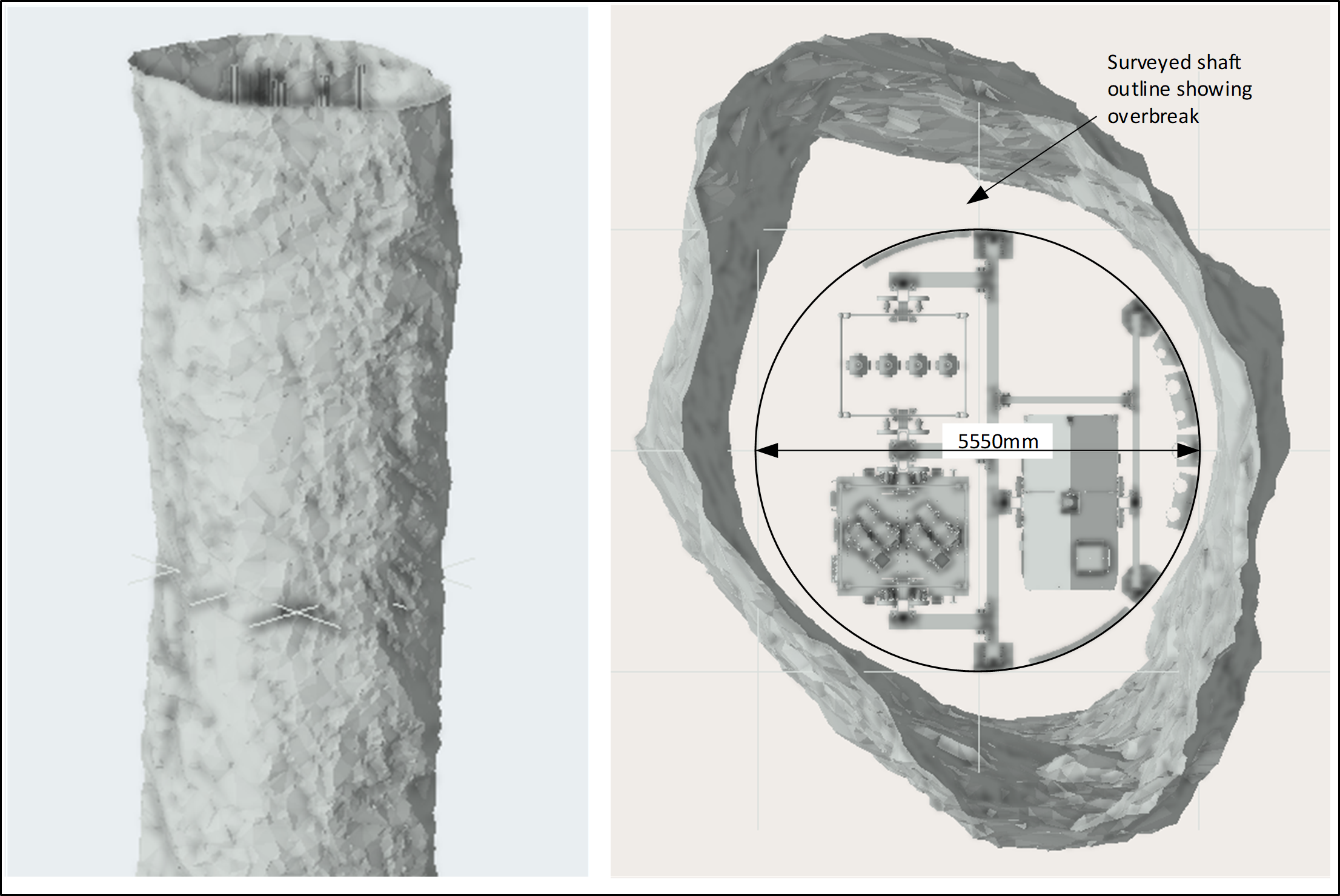
Figure 1. Survey of the excavated profile and cross section between 100L and shaft bottom.
Design criteria
The shaft sinking contractor will be installing piping and cables in the shaft during the first use of the pentice. During this phase the pentice needs to withstand an impact from a 6 m long, 200 mm nominal bore, schedule 120 pipe with a total weight of 550 kg falling just over 1000 m and reaching a velocity of 140m/s before impact.
Once raiseboring has been completed the pentice will be removed allowing for the final lining to be constructed down to shaft bottom. The shaft brackets for the buntons, piping and cables will be installed in the lower 160m from bottom-up following the completion of the lining. Once the stage is above the 100L, the pentice will again be installed on 100L to allow for the installation of shaft furniture above the pentice while the shaft bottom steelwork is installed below the pentice. The design criterion for second use phase was the heaviest piece of steel being installed, a 12m long top hat guide weighing 850 kg falling 1290 m and reaching a velocity of 160m/s.
Solution development
A literature review was undertaken at the start of the project to identify alternative structural solutions and generate ideas for further testing using LS-DYNA. Ideas tested included,
- a layer of sand over a concrete barrier
- large concrete beams and slabs
- various configurations of steel-concrete-steel (CSC) panels
- a lattice structure
- layers of steel plate with square hollow sections (SHS) as the final solution.
Solutions needed to be fabricated from materials with known material properties, because testing to verify their behaviour under high-speed impacts was not planned. The solution needed to be simple to fabricate and install, and not use any materials with properties that could be affected by the conditions in the shaft.
The choice and calibration of the material models in LS-DYNA has a major impact on the behaviour of the analytical model. Material models designed for high-speed impacts were used with different assumptions for the various structural components as noted below:
- A ‘rigid’ material property (MAT_020) was used for the falling objects (pipe and guide). This was to ensure that the full kinetic energy from the falling object is transferred to the structure and absorbed in the plastic deformation of the falling object.
- The LS-DYNA ‘Johnson Cook’ material model (MAT_015) was used for all structural steel components subject to impact loads. This material model is specifically designed for high-speed impacts and can be calibrated to the specific grade of structural steel used.
- For the steel support structure an elastic material model (MAT_003) was used to define the material properties for the structure which was to remain in its elastic range.
- A calibrated damage model (MAT_072R3) was used for concrete beams.
The outcome of the various solutions tested is summarised below:
- Using sand as an impact bed was dismissed due to the unpredictability of the behaviour of the sand over time due to water in the shaft.
- Various depths of beams and slabs were tested from 500 mm to 15000 mm. Based on the assumption that the falling object remains rigid, the concrete was found to be ineffective in stopping the falling object with the guide penetrating through the 1500 mm thick concrete.
- SCS panels of various thicknesses of steel and concrete were tested. It was found that the thicker steel plates slowed the falling object but the concrete between the plates was largely ineffective. Combinations of SCS panels stacked on top of each other with and without air gaps was also tested and found to be ineffective.
- A lattice structure showed promise, but the complexity of the structure and the number of welded elements eliminated this option.
- Based on the effectiveness of the plates in the SCS models tested, a solution was developed using layers of horizontal plates separated by layers of closely spaced square hollow sections (SHS). This solution was found to be effective in stopping the falling objects.
Design solution
Several different configurations were tested by varying the number of layers, the thickness of the steel plates, the size and spacing of the SHS members before settling on the layout shown in Figure 2.
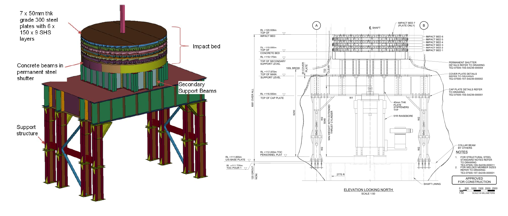
Figure 2: Final design.
The final design consists of:
- An impact bed made up of 7 layers of 50 mm, grade 300 steel plates separated by 6 layers of 150x9 SHS resting on 6 x 500 mm deep concrete beams cast into permanent shutters made from 16 mm plate.
- Secondary support beams to elevate the impact bed above the brow on 100L.
- A support structure consisting of four main portal frames tied together laterally spanning over the shaft and elevating the impact bed to above the raiseborer.
A literature review was undertaken to calibrate the input values used by the LS-DYNA material models. Listed in Table 1 are the parameters used in the analysis.
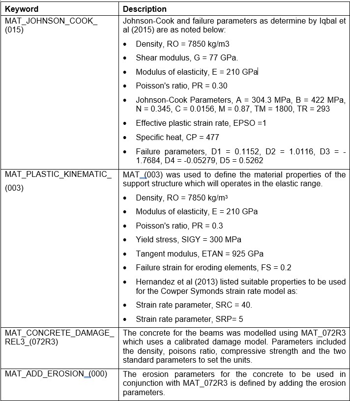
Table 1: LS-DYNA Material Model Parameters.
The adequacy of the impact bed and the design of the support structure was determined by applying the falling object at several locations across the surface of the impact bed. An impact on the edge proved to be the worst case for the impact bed, the support structure and for the reactions in the holding down (HD) bolts.
Figure 3(a) shows the damage done to the impact bed from a falling guide. The guide penetrates through 5 of the 7 layers of 50mm plate and deforms 6 layers of RHS before coming to a stop in 0.012s. Damage in the steel portion of the impact bed is fairly limited to the areas immediately around the impact point. Vertical reactions are shown in Figure 3(b) with the HD bolts closest to the impact point being in compression while those furthest away from the impact are initially in tension. At approximately 0.03s the maximum rebound force in the HD bolts is reached with large tensile forces evident in some of the bolts. The pattern continues with reducing effect over several cycles.
Damage to the concrete beams is shown in Figure 3(c) with the effective plastic strain in the concrete. Areas in red indicates where the concrete inside the permanent shutters has been damaged. Crack patterns in the beams not directly below the point of impact are also visible. Figure 3(d) shows the stress in the permanent shutters with the stress largely limited to the area below the impact. Figure 3(e) shows stress distribution in the support structure.
In all cases the impact bed was proven to be effective in stopping the falling object with varying degree of damage to the impact bed. The stress in the support structure remained in the elastic range.
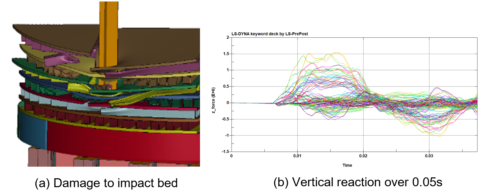
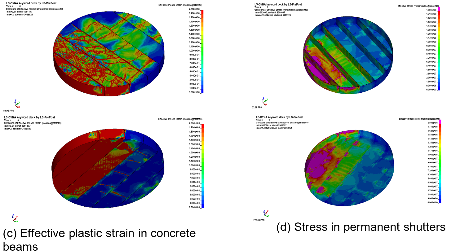
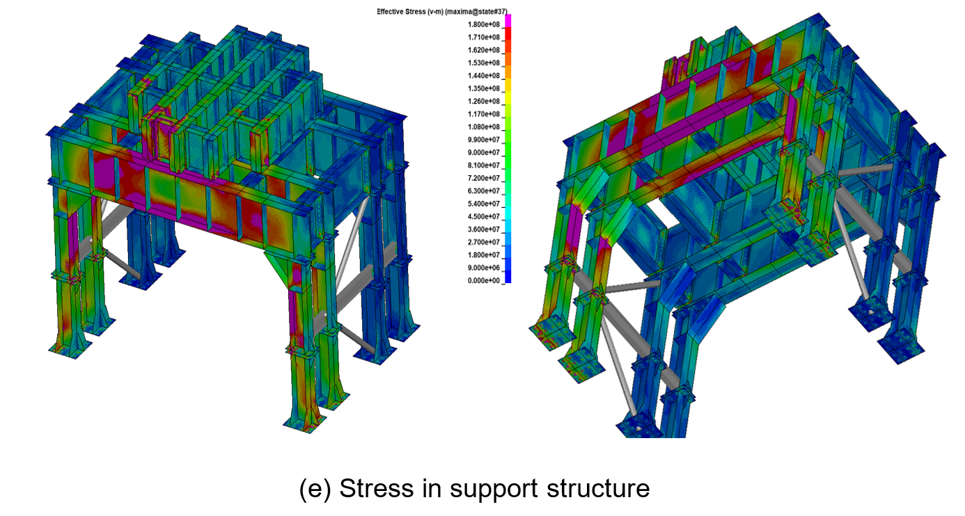
Figure 3: Final design.
Fabrication and installation
The steel impact bed of the pentice was modularised by splitting the 50mm steel plates into three potions with the SHS members welded to the plates before delivery. Alternative layers of the impact bed were rotated through 90 degrees and bolted together.
On site the pentice was partially trial assembled prior to the components being transported underground and assembled adjacent to the shaft. Enerpac 400 hydraulic jacks were used to move the structure over the shaft and then raise it into position before the bottom half of the columns were installed. The raiseborer was then driven in below the pentice and rotated vertically into position and set-up for operation.
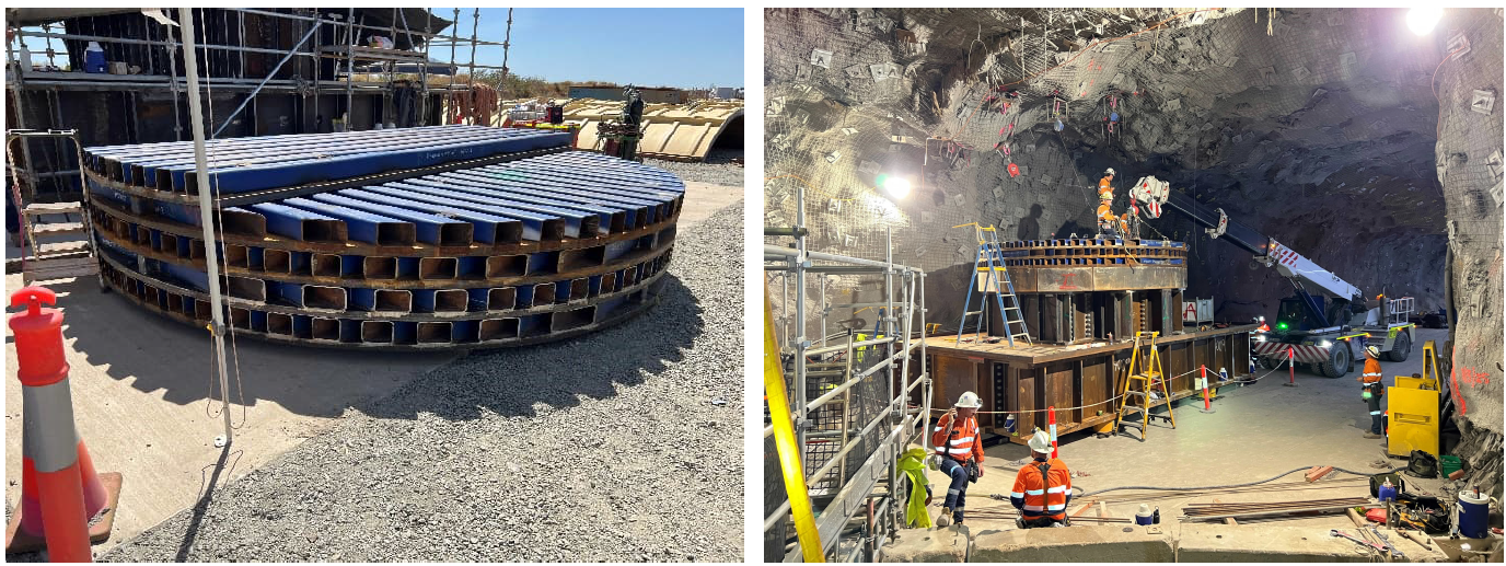
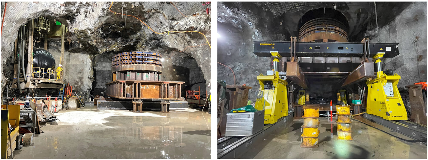
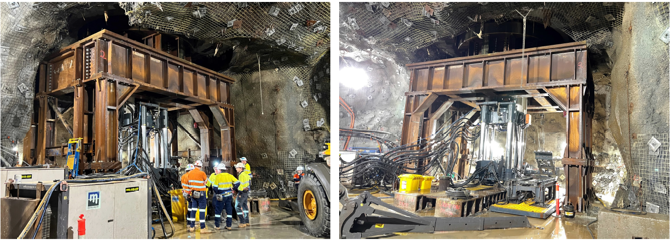
Figure 4: Installation of the pentice.
Conclusions
The design brief was to design a pentice for the Tanami TE2 shaft to withstand an impact from an 850 kg guide impacting the structure at 160 m/s. LS-DYNA was used to design an impact bed made up of 7 x 50 mm thick plates separated by 6 layers of 150x9 CHS members on a series of 500 mm deep reinforced concrete beams. This design was found to be adequate for a single impact and was found to stop the guide in approximately 0.012 seconds. A structure spanning over the raiseborer and shaft was designed to withstand the impact and rebound forces generated.
Acknowledgements
I would like to acknowledge Newmont and the TE2 Project for allowing this article to be published.
References
Hernandez, C, Maranon, A, Ashcroft, I A and Casas-Rodriguez, J P, 2013. A computational determination of the Cowper–Symonds parameters from a single Taylor test [online]. Applied Mathematical Modelling, 37: 4698-4708. Available from: < https://www.sciencedirect.com/science/article/pii/S0307904X12006154> [Accessed: 14 October 2024]
Iqbal, M A, Senthil, K, Bhargava, P and Gupta, N K, 2015. The characterization and ballistic evaluation of mild steel [online]. International Journal of Impact Engineering, 78:98-113. Available from: < https://www.sciencedirect.com/science/article/pii/S0734743X14003042> [Accessed: 14 October 2024]